For my Electronics for Applied Physics exam, I completed a master’s
project using an Arduino Nano 33 BLE Sense with its camera module to
capture images that were fed into a Convolutional Neural Network (CNN)
trained on the MNIST dataset. The work involved interfacing with the
camera module, handling serial communication protocols, preprocessing
the images, and running model inference on my machine. The main
technical challenge was integrating these components reliably, since any
point could fail and debugging proved difficult; by implementing custom
debugging and logging, I succeeded in the implementation. The code is
available at this link.
Serial
Communication and Arduino Integration
My implementation relied on the Arduino serial module to capture
pixel grayscale images by sending capture commands over the serial port,
triggering the camera to capture a frame into a buffer and stream the
raw frame data back over serial. The OV7670 camera module produces
176×144 pixel grayscale images, which amounts to 25,344 bytes per frame.
Transmitting this volume of data over serial at 115200 baud requires
careful buffer management to avoid timeouts and data corruption. The
Arduino sketch captures the frame into an internal buffer and then
streams it byte-by-byte over the serial connection, with the Python
server reading and reassembling the raw pixel data into a NumPy
array.
One significant challenge was ensuring reliable serial communication.
The Arduino Nano 33 BLE Sense uses a virtual serial port over USB, which
can be unpredictably enumerated by the operating system. To address
this, I implemented an automatic port detection function that scans all
available serial ports and identifies the Arduino by checking for
“Arduino” or “usbmodem” in the port description. Once a candidate port
is found, the function attempts to open a test connection to verify it
responds correctly before considering it valid. This approach eliminates
the need for manual port configuration and makes the system more robust
to USB enumeration changes.
Flask Server Architecture
To interface with the Arduino and simplify the process, I implemented
a Flask-based Python server that manages the connection, abstracts
low-level operations into Python arrays, and prepares the data for
processing. The server maintains a global serial_connection
object protected by a thread lock to ensure that only one request can
communicate with the Arduino at a time. This is critical because serial
communication is inherently sequential; if two requests attempted to
send commands simultaneously, the response data would be interleaved and
corrupted.
The image capture process is orchestrated by the
acquire_image function, which performs several steps in
sequence: first, it checks whether the Arduino sketch has been modified
since the last compilation by computing a SHA-256 hash of the source
file and comparing it to a cached value. If the sketch has changed, or
if the user explicitly requests a recompilation, the function invokes
the Arduino CLI to compile the sketch and flash the firmware. After
flashing, the server waits for the Arduino to reset and re-enumerate on
the USB bus, then re-establishes the serial connection. Only after this
process completes does the function send the capture command and read
the image data.
This automatic compilation and flashing system proved invaluable
during development because it eliminated a common source of bugs:
forgetting to upload modified code before testing. The server always
ensures that the running firmware matches the source code on disk, which
provides a strong guarantee that observed behavior reflects the current
implementation rather than a stale version.
Image Processing Pipeline
Processing begins by thresholding the image to create a transparency
mask, lighter pixels become transparent while darker pixels remain, then
resizing the image to
to match the CNN model trained earlier. The thresholding step is
necessary because the camera captures background noise and varying
lighting conditions, which can confuse the model. By setting a threshold
of 100 (on a scale of 0 to 255), pixels brighter than this value are
converted to fully transparent, while darker pixels are retained as
opaque. This creates a binary mask that isolates the handwritten digit
from the background.
In addition to matching the model’s input size, pixel values are
normalized to the
range and colors inverted to match the white/black convention of the
dataset. The MNIST dataset represents digits as white strokes on a black
background, but the camera captures dark strokes on a light background.
To account for this, the preprocessing pipeline inverts the pixel values
by computing
for each normalized pixel
.
This ensures that the input distribution matches the distribution the
model was trained on, which is critical for accurate predictions.
The resizing operation uses bilinear interpolation, which provides a
good balance between quality and performance. After resizing, the image
is converted to a single-channel grayscale array and expanded to shape
to match the CNN’s expected input format: batch size of 1, height 28,
width 28, and 1 color channel.
Next.js Web Interface
The user interacts via a Next.js web interface rather than directly
with the Flask API; the interface provides real-time visualization and
interactivity, allowing connection, disconnection, capture, and display
of the model’s prediction probabilities across all 10 digits as a bar
chart, giving immediate feedback on what the model sees and how
confident it is. The web interface communicates with the Flask server
via HTTP requests and displays the captured image as a base64-encoded
PNG, which is rendered in the browser alongside the probability
distribution.
The interface also includes a live logging panel that streams
messages from the Flask server, allowing the user to monitor the capture
process in real time. This proved essential for debugging because it
provides visibility into each step: port detection, sketch compilation,
firmware upload, serial connection establishment, and image reception.
Errors at any of these stages are logged with timestamps and severity
levels, making it straightforward to diagnose issues.
Arduino CLI Integration
Rather than using the Arduino IDE, I integrated the Arduino CLI into
the workflow. The command detects if the sketch has been modified; if
so, the server automatically recompiles the code and flashes the updated
firmware before attempting to capture images, preventing debugging
issues and ensuring the system is always in the expected valid state.
The Arduino CLI is invoked via Python’s subprocess module,
with the compilation and upload commands executed synchronously to
ensure each step completes before proceeding to the next.
The compilation step uses the fully qualified board name (FQBN)
arduino:mbed_nano:nano33ble to specify the target hardware,
and the output is written to a build directory in the
project root. The resulting hex file is then uploaded using the
arduino-cli upload command, which automatically detects the
bootloader and flashes the firmware. This process typically takes 10-15
seconds, during which the server blocks incoming capture requests to
prevent race conditions.
After flashing, the serial connection must be re-established because
the Arduino resets during the upload; this is handled automatically by
first closing any existing connection before flashing and then waiting
for the Arduino to enumerate on the USB bus again. The port detection
function is called again to locate the Arduino, and a new serial
connection is opened with the appropriate baud rate and timeout
settings. This automatic recovery mechanism ensures that the system
remains operational even after firmware updates.
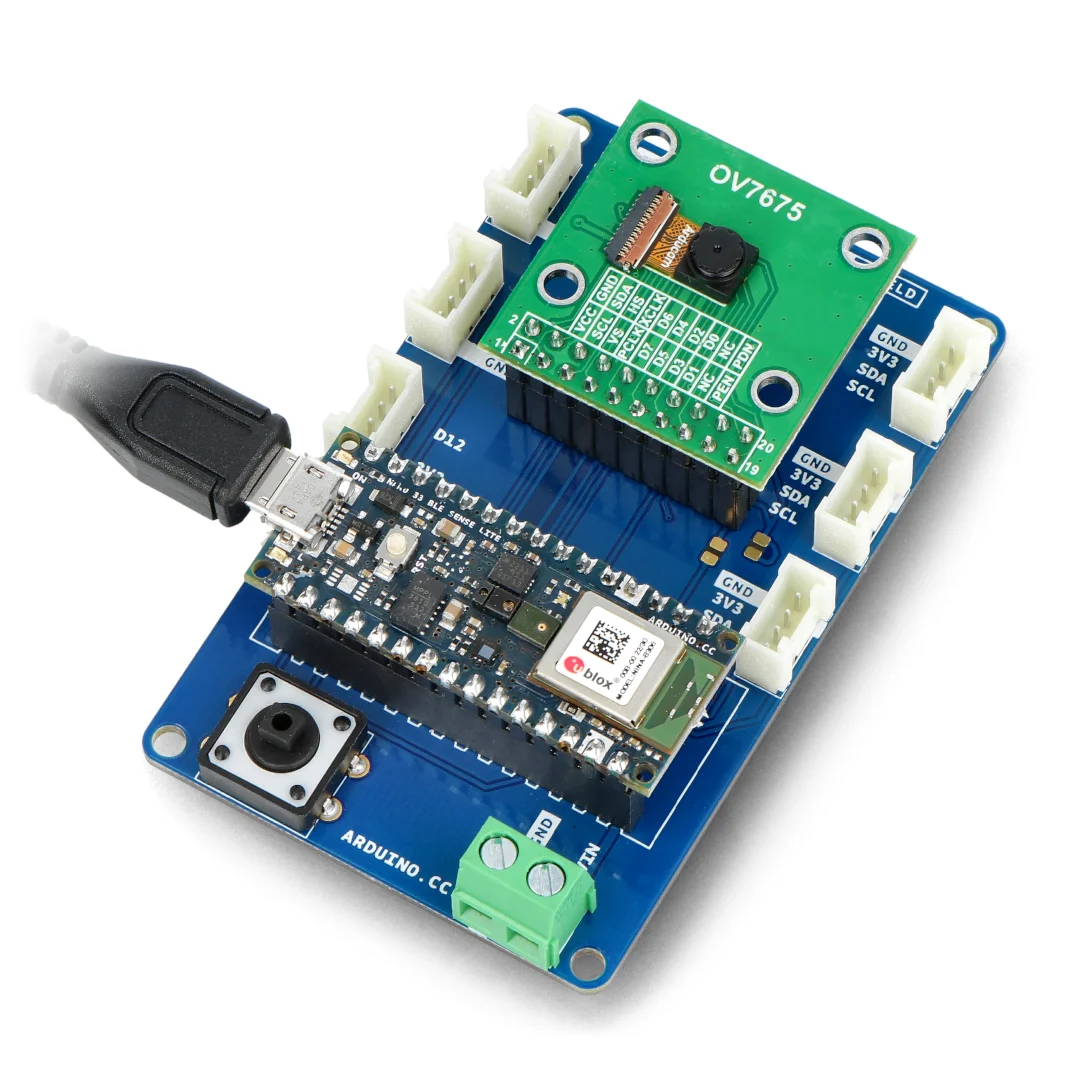
Unfortunately I have no pictures of the device, as it needed to be
returned to the professor, but here’s what it looked like:
Training the CNN Model
The digital recognition model is a standard CNN trained on the MNIST
dataset.
- Input:
For feature extraction it comprises two convolutional blocks…
- Conv2D:
filters,
kernel,
ReLU
- MaxPooling2D:
pool
- Conv2D:
filters,
kernel,
ReLU
- MaxPooling2D:
pool
- Flatten: Converts to
…followed by a classifier of fully connected layers with dropout for
regularization to prevent overfitting. The data are augmented with an
image generator that randomly rotates images up to 30 degrees and shifts
them horizontally and vertically by up to
,
which improves robustness when the digit is misaligned during camera
acquisition. The model is saved as a Keras file that the Flask server
loads for inference at runtime.
- Dense:
units, ReLU,
regularization
- BatchNormalization
- Dropout: Rate
- Dense:
units, ReLU,
regularization
- BatchNormalization
- Dropout: Rate
- Dense (Output):
units, softmax activation
The training process uses the Adam optimizer with an initial learning
rate of 0.001, which decays by 10% every epoch after the tenth epoch.
This learning rate schedule prevents the model from overshooting the
optimal weights in the later stages of training. I also implemented
early stopping based on validation loss to prevent overfitting; if the
validation loss does not improve for five consecutive epochs, training
terminates and the best weights are restored. After 15 epochs, the model
achieves a test accuracy of approximately 98.5% on the standard MNIST
test set, which is sufficient for real-time digit recognition.
Challenges and Debugging
One of the most frustrating aspects of this project was debugging
failures in the serial communication pipeline. When the Arduino failed
to respond, it was unclear whether the issue was in the camera
initialization, the serial protocol, the buffer management, or the
Python code. To address this, I implemented a comprehensive logging
system that records every step of the capture process with timestamps
and severity levels. The logs are stored in a thread-safe queue and
periodically flushed to the console and the web interface, providing
real-time visibility into the system state.
Another challenge was ensuring that the camera module was correctly
initialized. The OV7670 camera requires a specific sequence of I2C
commands to configure its registers, and any deviation from this
sequence results in corrupted images or no output at all. I spent
several days troubleshooting initialization issues before discovering
that the camera required a brief delay after power-on before accepting
configuration commands. Adding a 100ms delay resolved the issue and made
the system reliable.
The combination of automatic compilation, robust error handling, and
comprehensive logging transformed what initially seemed like an
insurmountable debugging challenge into a manageable workflow. By the
end of the project, I could modify the Arduino sketch, save the file,
and immediately test the changes without manually invoking the compiler
or upload tool. This tight feedback loop significantly accelerated
development and allowed me to focus on improving the recognition
accuracy rather than wrestling with tooling.